December 08, 2025
Desktop HVAC Lab Phase 1.5 — Bringing the CO₂ Sensor to Life
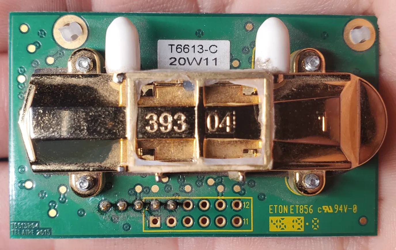
After getting my ESP32-based HVAC control project started the other week, the next big milestone was bringing in a real CO₂ sensor. I salvaged a Telaire T6613-C module from an old CO₂ sensor that had been retired due to damage. The case was cracked, the board was dusty, and I had no idea whether the sensing module still worked—or how far its calibration had drifted.
It turns out: pretty far.
The first step was desoldering the T6613 module from its carrier board. The original board expected 24V, but the bare module runs on just 5V, making it easier to integrate into my bench setup.
Step 1: Analog Output Testing
The breakout only exposes a handful of pins, but fortunately they’re the important ones: +5V, GND, an analog output, and a pair of UART pins. I wired the analog output into a simple voltage divider (2kΩ / 3kΩ) so the Arduino Uno could read the sensor’s 0–4V range safely.
Within a few minutes I had stable readings—high ones, though. Indoor CO₂ was showing around 1800–2000 ppm, which didn’t match reality. The sensor does long-term auto-baseline correction, so this confirmed the module had drifted way off zero after years in service.
Still, it meant the sensor was alive.
Step 2: Reverse-Engineering the UART Interface
The T6613 also exposes a UART interface using a simple binary protocol. Once I mapped the pins, I wired up SoftwareSerial on the Uno and sent the standard “read concentration” message:
FF FE 02 02 03
The module responded immediately with a five-byte frame beginning with:
FF FA 02 …
which is exactly what the protocol specifies. The problem was the reported ppm value—it was even higher than the analog signal, confirming that the internal baseline was severely miscalibrated.
At this point, I had two options:
- Let the sensor sit outdoors for a week or two and let ABC logic slowly re-learn the baseline
- Perform a manual single-point calibration using UART
I chose option 2.
Step 3: Full 400 ppm Calibration
The T6613 supports manual calibration using two UART commands:
1. Set the single-point target to 400 ppm
FF FE 04 03 11 01 90
(0x0190 = 400 decimal)
2. Start the calibration cycle
FF FE 01 9B
These must be sent in order, and the sensor needs access to actual fresh air while the calibration runs.
Because the Arduino Uno only has 2KB of SRAM, I wrote a very lightweight sketch to send the commands, wait 60 seconds, and read back the new value. After running the calibration outside, the readings dropped significantly and now tracked expected indoor levels.
At that point I knew: the module is healthy again.
Step 4: Logging Everything
With calibration done, I put together a simple logging setup:
- The Arduino reads both analog and UART CO₂ measurements every 5 seconds
- Output is printed as clean CSV lines
- A Python script on my home server captures each line with a timestamp and writes it into a CSV file for long-term trending
A sample log entry now looks like:
2025-02-01 23:14:55,120000,523,3.218,1609.0,1587
So I can graph:
- ADC raw values
- Corrected analog voltage
- Analog-derived ppm
- UART-derived ppm (now calibrated)
Seeing the two curves overlay nicely was a great confirmation that the calibration succeeded.
What’s Next
Now that the sensor is validated and logging reliably, it’s ready to join the rest of the desktop HVAC lab. The next step is wiring it into the ESP32 and integrating the data into my (in-progress) dashboard. Once that’s in place, I can start experimenting with ventilation control based on CO₂ levels: closing the loop from sensors to airflow.
More updates coming soon.
Related links
- Project repository:
https://github.com/desvert/ot-hvac-testbed